Hydraulic Structures
SCHISM represents a hydraulic structure as two paired internal boundaries. The model computes one total discharge from water levels at reference nodes, applies that discharge as an outflow on one boundary and an equal inflow on the other, and transfers tracers conservatively between the two sides. This mechanism supports prescribed transfers, weirs, culverts, rectangular orifices, radial gates, and compound weir-culvert structures.
This chapter describes both inputs used in a SCHISM workflow:
a geographic YAML description consumed by the schimpy preprocessor; and
the native
hydraulics.infile consumed by SCHISM.
The equations and file formats below have been checked against
src/Core/hydraulic_structures.F90 in SCHISM. They describe the implemented
behavior rather than a general-purpose hydraulic design model.
Mesh representation
Each structure consists of corresponding node pairs on opposite sides of a
barrier. The first member of every pair belongs to the nominal upstream side
and the second to the nominal downstream side. upnode and downnode are
reference nodes at which SCHISM samples water-surface elevation for the flow
calculation. Actual flow may reverse; the nominal orientation controls the sign
and selects the directional operating coefficient.
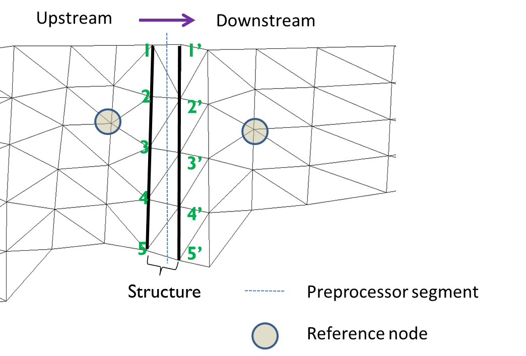
Fig. 1 A hydraulic structure imposed on the horizontal grid.
The paired node strings must span the channel and terminate on land boundaries. A gap around either end bypasses the structure. At least two node pairs are required. Reference nodes must remain wet, as is required for other SCHISM boundary nodes.
After SCHISM calculates the total structure flow, it distributes the flow as a
uniform flux over the paired boundary. The structure is not a geometric solid
inserted into the mesh. When a time series sets install to zero, SCHISM
removes the paired-boundary treatment and restores the ordinary equations of
motion across that part of the mesh.
Flow convention and relaxation
Let \(z_u\) and \(z_d\) be water-surface elevations at the nominal
upstream and downstream reference nodes, respectively. Positive discharge is
from the nominal upstream side to the nominal downstream side. SCHISM chooses
op_down for positive flow and op_up for reverse flow. An operating
coefficient of zero closes the structure in that direction.
The hydraulic equation produces a target discharge \(Q_s\). SCHISM relaxes the imposed boundary flow toward that target:
where \(\chi\) is the global nudging value in hydraulics.in. SCHISM
requires \(0 \leq \chi < 1\). Smaller values damp abrupt changes but also
slow the response to changing water levels and controls.
For the equations below, define
The configured coefficient, \(C_f\), is a nonnegative physical flow
coefficient. The sign of \(z_u-z_d\) supplies the flow direction. All
geometric and coefficient inputs describe one unit; SCHISM multiplies the
result by n_duplicates.
Supported structure types
transfer
A transfer prescribes a signed flow \(Q_s\) directly. Positive flow follows
the nominal upstream-to-downstream orientation. The hydraulic calculation does
not use water levels, operating coefficients, or n_duplicates. Tracer mass
is transferred from the outflow side to the inflow side.
weir
A weir can be dry, free flowing, or submerged. Its elevation is the crest
(or invert) elevation relative to the model datum and width is the width of
one unit.
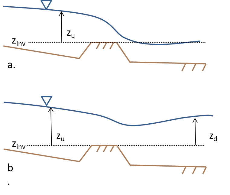
Fig. 2 Free-flowing (a) and submerged (b) weir flow.
With head above the crest
flow is zero when \(H \leq 0\). Otherwise the free-flow discharge is
When the lower water surface is above the crest, SCHISM applies the Villemonte submergence correction
The implementation uses water-surface head only; it does not add a velocity head at the reference node.
orifice
An orifice is a rectangular opening with invert elevation, width, and
height. The wetted opening depth and area are
Flow is zero for \(d \leq 0\); otherwise SCHISM uses
Thus an opening with tailwater below its invert uses upstream head above the invert, while a submerged opening uses the water-surface difference. No additional partially submerged correction is applied.
culvert
A culvert is modeled as a circular orifice. elevation is the pipe invert and
radius is the pipe radius (stored as width in hydraulics.in). For
wetted depth \(d\) and radius \(r\), SCHISM uses
The discharge equation and head term are the same as for an orifice. This is a simple circular-orifice representation; it does not choose among inlet-control and outlet-control culvert regimes or account explicitly for barrel friction and entrance, exit, or bend losses. Fold those effects into a calibrated flow coefficient when appropriate.
radial
A radial gate has invert elevation, gate width, and opening height.
The implementation uses the same rectangular wetted area as an orifice,
\(A=W\min(H_{gate},z_h-z_{inv})\).
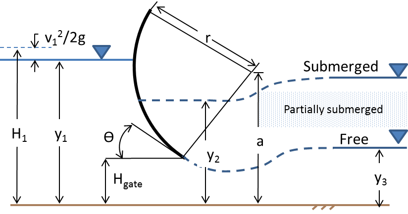
Fig. 3 Radial gate geometry.
Define the submergence ratio
SCHISM uses three regimes:
For \(S < S_p=2/3\), the free-flow equation is
\[Q_s = \operatorname{sgn}(z_u-z_d)\,C_{op}C_f A \sqrt{2g(z_h-z_{inv})}.\]For \(S_p \leq S < S_f=0.8\), it transitions linearly toward the submerged equation:
\[\begin{split}\widehat S &= \frac{S-S_p}{S_f-S_p}, \\ m &= \sqrt{\frac{1}{1-S_p}}, \\ Q_s &= \operatorname{sgn}(z_u-z_d)\,C_{op}C_f A \sqrt{2g\Delta z}\left[(1-\widehat S)m+\widehat S\right].\end{split}\]For \(S \geq S_f\), it uses the fully submerged orifice equation
\[Q_s = \operatorname{sgn}(z_u-z_d)\,C_{op}C_f A\sqrt{2g\Delta z}.\]
radial_relheight
This alternative radial-gate relation varies the flow coefficient linearly
with relative gate opening. In addition to coefficient \(d\), it takes
coefficient_height \(s\):
It uses the same rectangular wetted area as radial. The native SCHISM type
name is radial_relheight; the older name radial_rh is not accepted by
the current parser.
weir_culvert
A compound structure combines independent weir and circular-culvert units that share node pairs and reference water levels. SCHISM evaluates the weir and culvert with their own geometry, coefficients, directional controls, and numbers of duplicate units, then adds the signed discharges:
The weir can therefore be dry while the lower culvert continues to flow. The native input stores the weir as the main structure and the culvert as a substructure.
Geographic YAML input
The schimpy preprocessor converts geographic structure definitions to global
node pairs and writes hydraulics.in. Reference this file from the main
preprocessor input:
 hydraulics:
include: hydraulics.yaml
outputfile: hydraulics.in
A minimal structure file is:
nudging: 0.1
structures:
  grantline_weir:
    type: weir
    end_points:
      - [636576.0, 4186940.0]
      - [636575.0, 4187000.0]
    configuration:
      n_duplicates: 1
      elevation: 1.0
      width: 54.9
      coefficient: 0.8
      op_downstream: 1.0
      op_upstream: 1.0
      use_time_series: true
    reference: self
end_points gives the two ends of the structure span in the mesh coordinate
system. For a non-straight barrier, pathway may supply an ordered polyline;
gate_span then identifies the part of that path used as the paired hydraulic
boundary. The ends of the selected span must reach land boundaries.
reference is optional and defaults to self. With self, schimpy
selects reference nodes on opposite sides of this structure. A structure may
instead name another structure and reuse its reference pair, which is useful
for adjacent weir and culvert definitions that must use identical heads.
Configuration keys
The following keys use underscores. They are values for one physical unit unless noted otherwise.
Type |
Configuration keys |
|---|---|
|
|
|
|
|
Weir keys plus |
|
Orifice/radial keys plus |
|
Weir keys, with |
|
Weir keys plus |
For example, a culvert that uses the same reference nodes as the preceding weir can be written as:
grantline_culvert:
  type: culvert
  end_points:
    - [636576.0, 4186918.0]
    - [636576.0, 4186940.0]
  configuration:
    n_duplicates: 6
    elevation: -1.28
    radius: 0.61
    coefficient: 0.6
    op_downstream: 0.0
    op_upstream: 1.0
    use_time_series: true
  reference: grantline_weir
Native hydraulics.in input
Set ihydraulics = 1 in the SCHISM parameter file to enable hydraulic
structures. The native file begins with two global records:
number_of_structures
nudging
Each structure then has this common prefix:
index name
number_of_node_pairs upstream_reference_node downstream_reference_node
upstream_node_1 downstream_node_1
...
upstream_node_N downstream_node_N
structure_type
n_duplicates
Indices must be sequential, names are limited to 32 non-whitespace characters,
and all node numbers are global. At least two node pairs are required. The type
specific records follow n_duplicates.
Type |
Records after |
|---|---|
|
|
|
|
|
|
|
|
|
Weir |
The final record in every structure block is use_time_series: zero disables
time-series control and any nonzero value enables it. Thus a complete native
weir block resembles:
1
0.1
1 grantline_weir
3 120 126
121 125
122 124
123 127
weir
1
1.0 54.9
0.8 1.0 1.0
0
Time-series control
When use_time_series is enabled, provide NAME.th in the SCHISM input
directory, where NAME exactly matches the structure name. The first column
is elapsed model time in seconds. The second is integer install: zero
removes the structure and one installs it. Subsequent values replace selected
values from hydraulics.in.
SCHISM advances these irregular time histories using stepwise changes rather than linear interpolation. Include a record applicable at the beginning of the run. The exact columns are:
Type |
Columns |
|---|---|
|
|
|
|
|
|
|
|
The time series does not update coefficient or coefficient_height for
any structure type. For weir_culvert, it does not update either component’s
flow coefficient.
Implementation limits and modeling cautions
The current implementation has several deliberate simplifications that should be considered during calibration and model design:
Reference head is water-surface elevation; velocity head is omitted.
Culverts are circular orifices, not a full culvert inlet/outlet-control model.
Orifices and culverts do not receive the weir’s Villemonte submerged-flow correction.
Radial-gate transition thresholds are fixed at \(2/3\) and \(0.8\).
Flow is distributed uniformly across the paired boundary rather than resolved through the physical opening.
Time-series changes are stepwise, and flow relaxation means the imposed flow does not jump immediately to the newly calculated target.
These limits do not prevent calibration, but the fitted coefficient represents all unresolved contraction, loss, and geometric effects. Validate flow direction, reference-node wetness, crest or invert datum, duplicate count, and operation in both directions before relying on a structure in production.
References
Bodhaine, G. L. (1968). Measurement of peak discharge at culverts by indirect methods. U.S. Geological Survey Techniques of Water-Resources Investigations, Book 3, Chapter A3.
Rantz, S. E., and others (1982). Measurement and computation of streamflow, Volume 2: Computation of discharge. U.S. Geological Survey Water-Supply Paper 2175.
Villemonte, J. R. (1947). Submerged-weir discharge studies. Engineering News Record, 139(26), 54–56.